The SubFlow processor serves two purposes in Elixir Data Designer. Firstly it allows complex flows to be abstracted by defining modular sub-flows to aid comprehension of the diagram. In this role, a SubFlow acts like a subroutine call. In addition, SubFlow allows a single flow to be split into multiple branches based upon conditions. Each sub-flow may then perform a different sequence of actions, for example storing the records to disk, deriving values where data is missing etc. In this role, a SubFlow acts like a switch statement in a programming language.
The SubFlow processor is selected from the menu bar of the Designer window and then placed on the diagram.
The only editable properties of a SubFlow are name and colour. Double-click on the graphic, or choose View Diagram from the popup menu to open the nested diagram. You need to join the Input to the Output, with one or more flows, so that the records can be passed back to the parent flow. When acting as a subroutine, there is typically a single flow of processors between Input and Output. When acting as a switch there may be several flows in parallel. The flow in Figure 4.37, “SubFlow Sample” shows a switch-style flow.
To switch back to the parent diagram, choose the Close button from the subflow toolbar.
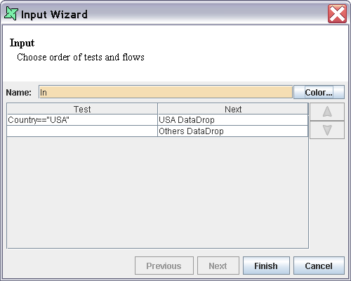
The Input graphic on the SubFlow diagram allows you to set a series of tests that are applied to choose between the different parallel flows. The wizard is shown in Figure 4.38, “Input Wizard”. This screenshot is taken from the SubFlow Sample above and shows how those records with Country value "USA" are passed to the USA DataDrop part of the flow and the rest (those with no test) are passed to the Others DataDrop. The Input tests proceed in order from top to bottom of the list. The first test that returns true indicates the record is passed to that flow. Subsequent tests are ignored. An empty test is considered true, and so all records that have not already tested true will pass to the first empty test flow.
The test order can be controlled by moving the rows up and down in the table. If no test returns true, the record will be discarded. The tests will be shown on the diagram as labels attached to the appropriate flow. You can reposition the labels by clicking on them and adjusting the positions of the handles.
Note
The names of processors connected to the Input should be unique to make it easier to determine which flow corresponds to which test.

